
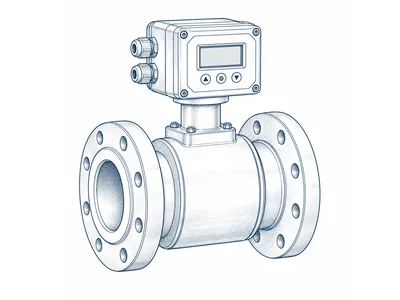
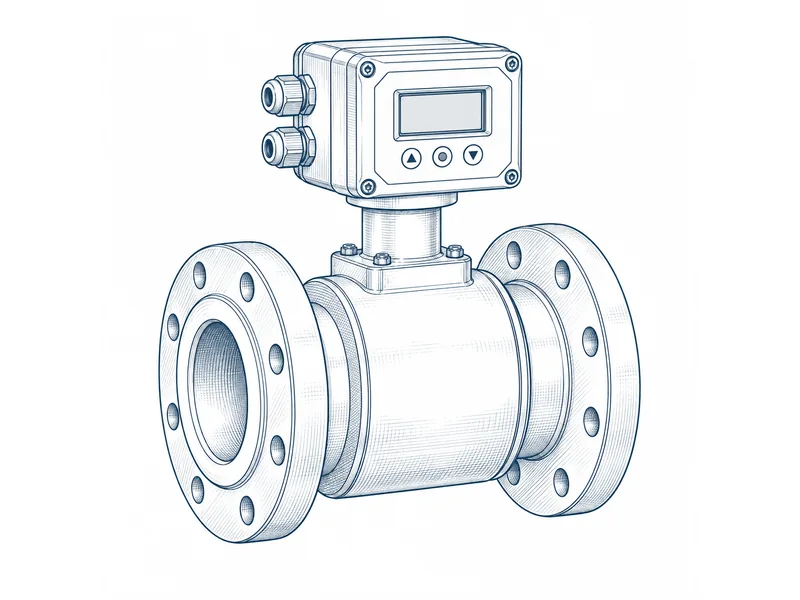
MODEL OVERVIEW
What the FM15/R offers
- Remote electromagnetic
- 5 m transmitter cable in list, longer cable optional. Obtain the complete remote configuration sheet
- do not infer all integral specifications.
Manufacturer’s documented description: Fedrel product and price list, effective 20 January 2026, pp. 8–10. Options and qualifications above are retained as stated.
Check these document differences
Document editions
Fedrel FM15 catalogue, revision 2022, pp.2–3: size, pressure and power/output options
Fedrel effective 20 January 2026 list pp.8–10: separate integral, remote, battery and telemetry configurations. Obtain exact-configuration drawing; do not combine all options
Request written confirmation for the offered size and configuration before using either value.
TECHNICAL DATA
FM15/R specifications
| Parameter | Documented value |
|---|---|
| Measuring principle | electromagneticFedrel product and price list, effective 20 January 2026, 8–10 |
| Installation style | Remote display with 5 m wireS17 · 9 |
| Nominal diameter (DN) | 15, 20, 25, 40, 50, 65, 80, 100, 125, 150, 200, 250, 300, 350, 400, 450, 500S17 · 9 |
| Accuracy statement | ±0.5% as printed; basis not stated in this blockS17 · 9 |
| Fluid temperature | −20 to 150°C family block; exact liner limit must be confirmedS17 · 9 |
| Wetted materials | SS316L electrode; PTFE / hard-rubber liner optionsS17 · 9 |
| Connections | ASME B16.5 Class150 flangesS17 · 9 |
| Sensor protection | Sensor IP68S17 · 9 |
| Transmitter protection | IP65S17 · 9 |
| Power supply | 220 VACS17 · 9 |
| Included outputs | 4–20 mA, pulse and RS485 Modbus RTUS17 · 9 |
| Body material | SS304 flow tube; carbon-steel flange/coil housingS17 · 9 |
| Pressure designation | PN16S17 · 9 |
| Optional accessories | Longer transmitter cable; tri-clover/wafer or other flange drilling on requestS17 · 9 |
Fedrel FM15 / FM15R: 2022 dimensional schedule
S22 p.2, revision 03, 27 May 2022
Older standard-pressure schedule changes to PN10 from DN200; the 2026 product blocks state PN16. Confirm offered pressure, mounting and drawing. A dash means no weight stated.
| DN (mm) | Flange OD (mm) | Length (mm) | PCD (mm) | Bolts / holes (mm) | PN | Minimum (m³/h) | Maximum (m³/h) | Weight (kg) |
|---|---|---|---|---|---|---|---|---|
| 25 | 108 | 200 | 79.2 | 4 × 15.87 | 16 | 0.27 | 13.7 | 7 |
| 32 | 117 | 200 | 88.9 | 4 × 15.87 | 16 | 0.55 | 27.2 | 8 |
| 40 | 127 | 200 | 98.6 | 4 × 15.87 | 16 | 0.75 | 37.7 | 8 |
| 50 | 152 | 200 | 120.6 | 4 × 19.05 | 16 | 1.35 | 66.5 | 9 |
| 65 | 178 | 200 | 139.7 | 4 × 19.05 | 16 | 2.1 | 105 | 10 |
| 80 | 190 | 200 | 152.5 | 4 × 19.05 | 16 | 3.25 | 163.5 | 12 |
| 100 | 229 | 250 | 190.5 | 8 × 19.05 | 16 | 5.75 | 289 | 21 |
| 125 | 254 | 250 | 215.9 | 8 × 22.22 | 16 | 9.2 | 460 | 23 |
| 150 | 279 | 300 | 241.3 | 8 × 22.22 | 16 | 13.25 | 662 | 26 |
| 200 | 343 | 350 | 298.4 | 8 × 22.22 | 10 | 23.3 | 1166 | 42 |
| 250 | 406 | 400 | 362 | 12 × 25.40 | 10 | 36.5 | 1825 | 64 |
| 300 | 483 | 500 | 431.8 | 12 × 25.40 | 10 | 52.3 | 2605 | 94 |
| 350 | 533 | 500 | 476.2 | 12 × 28.57 | 10 | 64.25 | 3214 | — |
| 400 | 597 | 600 | 529.8 | 16 × 28.57 | 10 | 85 | 4249 | — |
| 450 | 635 | 600 | 577.8 | 16 × 31.75 | 10 | 109 | 5440 | — |
| 500 | 693 | 600 | 635 | 20 × 31.75 | 10 | 135 | 6738 | — |
| 600 | 813 | 600 | 749.3 | 20 × 34.92 | 10 | 199 | 9916 | — |
| 700 | 927 | 700 | 863.5 | 28 × 35 | 10 | 270 | 13470 | — |
| 800 | 1060 | 800 | 978 | 28 × 41 | 10 | 349 | 17435 | — |
| 900 | 1168 | 900 | 1086 | 32 × 41 | 10 | 444 | 22160 | — |
| 1000 | 1289 | 1000 | 1200 | 36 × 41 | 10 | 546 | 27283 | — |
Details to confirm for the offered configuration
These parameters are not established as exact-model values in this record. Some may not apply to this technology.
- Q1 m3 h
- Q2 m3 h
- Q3 m3 h
- Q4 m3 h
- Working pressure and temperature
- Approvals and scope
DUTY & SELECTION
Where to consider this type
An electromagnetic meter, often called a mag meter or EMF meter, measures flow using the electrical signal induced when a conductive liquid moves through a magnetic field.
Installation and commissioning
Before the meter is selected
- Lowest measured conductivity
- Liner, electrode and seal compatibility
- Full measuring tube, grounding and pipe profile
- Integral/remote configuration, accuracy basis and simultaneous powered outputs
Before the system is handed over
- Confirm the installation drawing, orientation and access for service.
- Match the actual flow range and permitted pressure loss to the project.
- Record meter serial number, start reading and any output scaling.
- Commission communications against the receiving system and retain the test record.
Reading and communication
No electronic output is established for the base record. Confirm a compatible pickup or communication variant if remote reading is required; do not assume another model’s output can be fitted.
Understand pulse, wired and wireless reading ↗Documents and purchase checks
Read the Fedrel technical reference → · Browse the source index
Source: Fedrel product and price list, effective 20 January 2026, pp. 8–10. Reviewed 2026-09-09.
Ask for these before ordering
- Approved drawing for the exact model, size and configuration
- Serial-number calibration or factory test record
- Applicable approval certificate and exact scope
- Installation manual and required straight pipe
- Protocol/register map and output power requirements
- Option/accessory codes with included components
- Pressure-loss curve, flange drilling and face-to-face length
- Current written commercial and warranty terms
SPECIFY YOUR REQUIREMENT
Get a quotation for FM15/R
Tell us the size and quantity you need. Add the fluid, flow or output requirement if known. You can review and send the enquiry from your email app on the next page.
Compare related models
Similar technology does not mean equivalent performance. Compare exact configurations.